

| CBMSTEVE.CA - Personal pages of Steve J. Gray |
| Changes | Info | Prototypes | Remakes | PET Projects | CBM Projects | Modding | 3D Models | KiCad | Github | Ohio Scientific | Other | My Software | My Collections | Facebooks |
Welcome! This is a project to recreate a "Commodore LCD" computer (aka CLCD). The CLCD was a prototype laptop computer that was in development in 1984/85 and reached pre-production stage. Unfortunately it was cancelled in favour of the C128 computer. Only a handful of these computers were made and few survived. Luckily system specifications, firmware, and schematics were saved. Firmware from Bil Herd's early prototype were dumped many years ago. Recently Jeff's firmware was dumped and it appears that both versions are very similar. Hopefully that means that the hardware was stable. Additional investigation of Jeff's firmware is needed to see what has been changed.
For a long time I have been interested in this machine, as it had the potential to be a game-changer. Bil had managed to save the schematics, but until recently one page was missing. Finally the missing page was found and the schematics scanned and finally released in 2022, which motivated me to start this project. This is a multi-faceted project to create a CLCD work-alike machine, not in an exact duplicate, but in a form that is more up-to-date, using newer still-available chips. Since the LCD panel, custom gate arrays, keyboard and case are not available we need to find alternate solutions. This project is also a way for me to learn CPLD programming, as well as using PLCC chips, and modern implementations of the CPU and VIA chips.
All pcbs will be designed with Kicad. The case will be designed with Sketchup (free web version). Full design files will be made available when they are usable.
This will be a team project with myself and Mike Naberezny. Mike has much more electronics experience than I do, and also has designed and built Single-Board Computers. Mike has also done extensive disassembly of the CLCD KERNAL and can write firmware to test each component of the pcb.
The main PCB schematics were studied and I determined that we could make a mostly compatible design with modern versions of the chips such as the CPU and VIA's. However the Custom Gate arrays, which include the MMU and the LCD controller, would need to be re-created. Since the LCD panel is not available it didn't make sense to try re-creating it. Instead The video subsystem has been replaced with a Commodore 8563 VDC chip from the C128 computer, and a dual-port SRAM that also doubles as the system's main 32K ram. The VDC chip should be able to emulate the 6x8 font format as well as the 128-bytes per screen line that are unique to the CLCD machine.
The CLCD used a 65C102 DIP cpu. These are hard to find now. Instead I have replaced it with a 65C02 which is fully code compatible and comes in PLCC format in speeds up to 14MHz. It may be possible to clock the machine at higher speeds with the use of more modern IO, RAM and ROM chips.
I have included 512K of RAM on top of the 32K DPRAM which will act as extended RAM memory. I have also included 1MB of ROM that can hold all of the KERNAL, MENU, and APPS that were in the CLCD prototype. There is more RAM and ROM than on the original machine but perhaps the additional memory can be utilized in the future.
There are two VIA chips just like the original. These control Keyboard, IEC, RS-232, centronics, RTC and barcode scanner funtions. The CLCD had an internal modem but it doesn't make sense to include it. The barcode port will not be included, however there is a header. I include a video port, serial port, centronics port, iec port and internal iec header, power jack and switch, and a reset button along the back of the pcb in the initial design. Future designs may change.
The CLCD's video was designed to drive a custom LCD panel. As such, it's not possible to duplicate it. The LCD panel was quite advanced for it's time however technology has come a long way since then. I am familiar with the old 6545 CRTC controler as found in the PET/CBM line. The C128's VDC chip is like a CRTC chip on steroids. I looked into it and discovered it is capable of handling 6x8 pixel fonts and 128 byte per row screen formats. The VDC chip poses some challenges as this chip was designed to use local video ram that is accessable only through the VDC registers. This would not work with the CLCD, however the solution I came up with is to use a 32K dual-port SRAM that can be accessed by the VDC and CPU independently. As the VDC has a 64K address space, I have mapped the FONT ROM and some ram into the upper 32K. This means the font pointer just needs to point to it during initialization and will be hidden from the CPU as in the real machine. You can also select RAM to be there so that you can program your own fonts, or do graphic screens. Lastly, the VDC supports colour and so we could theoretically add that capability in the future.
The original CLCD machine was battery powered. This function will not be implemented for the first pcb.
PCBs have arrived and I am populating the board and gathering parts. Mike also made a set of boards and has been populating each section and testing each section to make sure it works before moving to the next section. Mike has been identifying mistakes and possible issues with my pcb design and jerry-rigging the fixes on the board. Mike's board is now at a working stage. It will boot a slightly modified KERNAL
STATUS:
- WORKING: Reset, CPU, RAM, ROM, DPRAM, VDC, FontROM, Centronics, ACIA, IEC, Keyboard
- UNTESTED: RTC, VDC Upper RAM


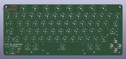
The CLCD keyboard is unique for Commodore. It is compact and has 8 function keys and a 4-way cursor block. In many ways the keyboard is similar to the Plus/4 keyboard but is less wide. The keycaps are low profile. Electrically, the keyboard has an 8x8 main matrix and an additional separate modifier matrix. Also unique to this keyboard is the way it's connected to the computer. It uses two shift registers to read the keys serially. This allows the keyboard to be read with less lines, and also reduces the key ghosting that is common when pressing multiple keys at the same time.
I have designed several different MX replacement keyboards for Commodore machines, so doing the CLCD keyboard was pretty straight-forward. I decided to make two designs...One with arrow keys like the Plus/4 and a second with inverted-T cursor using MX switches. I used the keyboard matrix from documentation. I initially thought that the REV2 keyboard was connected differently than the REV1 keyboard but that seems not to be the case.
I found one VIA that was missing on the PCB causing a whole ROW to not work. It's now fixed. Mike was able to test the keyboard and found that the ROWS and COLS needed to be re-wired on the CLCD motherboard but now the keyboard is fully working with the REV1 firmware!
Mike and I had a few keyboard pcb's made of the inverted-T design and they have been assembled using standard MX switches. Custom cherry mx keycaps have been designed and have arrived. There was one missing VIA on the first revision but that was easily fixed.
STATUS: Inverted-T cursor version complete. Exact keyboard layout for resin-printed keycaps in progress.

For MX keycaps I decided to use MaxKeyboard.com again like I did for the V364 project. They offer a Custom Color Printed Keycaps service that uses a dye-sublimation process. Each key can be a different colour, from a choice of over a dozen colours. You provide the vector artwork for each key using their keyboard templates. You can put basically anything you want on each key. To recreate the CLCD keyboard I used a high-resolution scan of an actual bare CLCD keyboard provided by Bo Zimmerman. I matched the font and symbols as best I could, and created the graphics symbols all in vector format. I selected the 104 key layout in order to get enough keys of the proper size and key row. There were extra keys which I used to make some alternate versions of some keys (ie: letter keys without the numeric pad) and a few other keys. I used beige keycaps for the CLCD keys, but I also did an extra set of F-Keys in rainbow colours so I could have samples of the different colour keycaps that they offer. I also made some extra C= keys for fun!
The low profile keycaps pose a problem. I havent found any mx keycaps that are available to match yet. I have seen commerical keyboards with very similar caps (I have a couple) but they are not MX compatible. The keyboards I have seen are dome type with a conductive rubber pad that shorts two pads on the pcb. We can make a similar pcb, but would need some type of custom made frame that would accept the keycaps, and a custom rubber dome underneath. Because of this I decided to go the MX route first to have a working keyboard.
I do have some ideas about making a better, more accurate keyboard. I recently purchased a high-resolution resin printer which will give us the ability to create very accurate low-profile keycaps, as well as making correct size MX-compatible function-keys. The function keys are very wide and slim and I have not seen any commercial keycaps that come close. The first non-test resin prints I did were the CLCD function keys. I downloaded an MX keycap and used the stem from that, but replaced the top part with a simple rectangular block like the actual keycaps. These did not fit. Upon checking I discovered that the stem dimensions were too small. I adjusted the sizing and added some bevelling to the bottom face as well as the internal post hole. I reprinted them and they fit! Low-profile keycaps for the rest of the keyboard are in the works. We can still use standard MX switches and the existing inverted-t keyboard design but with much better looking keycaps. Once that is done I will look into re-designing the PCB to be an exact replica of the CLCD keyboard layout including the arrow-shaped cursor keys.
STATUS: In Progress. Custom Cherry MX Keycaps complete. Resin MX keycaps in development.


Since the original LCD Panel is no longer available I looked for a panel about the same size. I found a colour panel that is almost the exact size, but not with the same pixel resolution as the CLCD. I have chosen a 10.3" Ultra Wide LCD screen with part# CLAA103WA01 with 1280x480 resolution. It has a 60-pin ribbon cable plus a backlight connection. I purchased 2 of them. Both came with the same display controller. One was from ebay and the other was from AliExpress. The price ranged from $70 to $100 CAD. The controller supports HDMI, VGA, and composite inputs. I found the composite connection to be sub-par quality and so I recommend using the HDMI connection and an RGB2HDMI adapter. Since the CLCD's screen resolution is 480x128 it will not be possible to provide a pixel-perfect CLCD display.
My CLCD board is not complete so I have written a program called VDC Explorer (VDCX)" that lets me play with the VDC registers on C128 to generate different screen parameters, which can be used to initialize the VDC depending on the installed panel. This program lets me load fonts and screen dumps to simulate the CLCD screen output. The VDC chip is very flexible and can be programmed to generate a wide variety of outputs. It is similar to the PET's CRTC chip but with additional registers for the advanced features such as soft fonts, character width, bitmap modes, and colour.
I will be feeding the CLCD's video output to an RGB2HDMI. It can be configured to accept a video signal, process it, and re-format it to modern HDMI displays. The CLCD's 80x16 screen format poses a problem in that it does not look like a typical NTSC, PAL, EGA, VGA or other video standard. Luckily in the current RGB2HDMI release (as of 2023-05-17) software it now supports 128-pixel tall screens, allowing a full edge-to-edge display on the 10.3" widescreen LCD Panel.
The RGB2HDMI takes a full NTSC-format display and scales the active 80x16 area to fill the entire LCD panel. It turns out that there was no need to modify the VDC to produce some sort of weird non-standard sync display. The output of the RGB2HDMI produces an output that is very similar to what would be displayed on the real CLCD panel. And, as a bonus, the RGBI connector on the back allows simultaneous display on an external monitor!
STATUS: Complete.


The CLCD case is also unique. It has a flip-up screen with keyboard cover attached. It's kinda styled like the 64C and C128 but with the screen added. My goal is to design and 3D print a replica case. The current pcb is also fairly small so it's also possible to house it in a standard C64, Plus/4 or similar case for debugging the design.
I have designed a preliminary case using Sketchup. I used pictures and videos of Bil's prototype, pics of Jeff's pre-production machine, and dimensions provided by Bil and from the brochure as reference. A full-size case has been printed using an Anycubic Kobra Max printer, which is big enough to do each piece full size. This case holds the pcb, keyboard, LCD panel and controller/backlight board, as well as an RGB2HDMI and the LCD controller button-board.
I am using brass screw inserts to secure controller boards to the case, and to assemble the top and bottom case pieces together. I needed a lot of practice to get the inserts to melt into the plastic properly so that they were secure.
Due to the small size of the case, fitting the display electronics was a challenge. The RGB2HDMI and LCD controller buttons needs to be available. Originally I was going to mount the RGB2HDMI on the bottom with a small window for the buttons. After a lot of thought I decided to locate them in the battery compartment area. As seen in picure below this was not easy. In fact there is only a few millimeters of clearance between the VIA chip and the RGB2HDMI board. Cable management was also tricky, but in the end it all worked out. As the display is connected via HDMI the VGA and composite connectors can be removed for a bit more space.
I tried to find a filament colour that was close to the original. I chose a Light-beige EconoFil PLA from Filaments.ca. The PLA seems to print fairly well. PLA printers are good, but surfaces are not perfect. I am investigating options for filling, sanding and painting the case. I am also working with Bil to find the best colour match for the prototypes. Also, since Mike's visit to Jeff and the new pictures of Jeff's prototype I will be refining my case to more closely match his. This will involve rounding off edges and adding more detail.
STATUS: Full workable case!


The REV1 firmware was disassembled by LGB and he created a CLCD emulator. Much information can be found on his CLCD pages. The firmware was further disassembled and commented by Mike Naberezny and is currently in a state that it can be re-assembled into a working binary. This source code will be used in this project but will need to be patched to support the VDC video chip. Because of this, the re-created machine may not be entirely compatible with the original but hopefully will be compatible enough to be workable.
The CLCD has an interesting architecture where it maps in large chunks of ROM code as needed. The KERNAL is a full 32K in size. Luckily there are large empty areas for implementing patches etc. In fact, there are large chucks of code from the C128 left in there presumably from firmware development.
The CLCD has an 80x16 format display, which is a bit odd for today. The VDC chip can be programmed for the same format but we have to adjust it to conform to current display devices. It's also possible to program the VDC to use double-height fonts that can stretch the display to fill the screen top to bottom.
Mike has been working on the firmware. He has been creating small test KERNALs using code from the real KERNAL to debug the pcb design and confirm functionality.
On May 20/2023, Mike visited Jeff Porter and was able to dump the contents of his machine, so we now have the "final" (hopefully) ROM release. These should be the same ROMs that were in the demo machines that Commodore displayed at their introduction however it's possible that additional development was done after the show and before the project was cancelled. The ROMs seem to be functionally the same as Bil's ROMs but without the extra leftover code from the C128 that was left in during development. More investigation is required before we can attempt to use these ROMs in our re-creation.
STATUS: Working with only a small patch to initialize the VDC.
The MMU gate array has been replaced with a modern (well, relatively speaking) Altera MAX7128 5V chip. This will be the main chip that provides all the memory mapping, custom control registers and chip select lines. I have never done any CPLD programming so this will be the most challenging part of this project. The current pcb has headers for all the CPLD lines for debugging purposes.
Mike has taken up the task of starting the CPLD programming. Currently he has been able to get the CPLD to do the basic address decoding and chip select generation. This means the EPROM-PLA board is no longer needed! Mike is now working on implementing the MMU.
STATUS: In Progress.
I have made a small pcb that mounts on the expansion header and chip-select header that implements an EPROM-based PLA-type circuit for initial testing, with simple debug firmware. Mike has written a python program that generates the binary for the eprom. Now that CLPD programming can duplicate this functionaliy the EPROM-PLA board is no longer necessary.
STATUS: Complete. EPROM-PLA board is working. Now redundant.
The project has been posted on Github here. Includes V1 Prototype pcb, keyboard, keycaps, and 3D case design.
I have created a Facebook Group for the CLCD. Hopefully this group will be a source of information and discussion and a place for people who are interested in all aspects of the machine to interact. I will be posting periodic updates on my project there.
The following are resources used in this project:
Here are some pictures of the project in chronological order:


![]()
Created: June 21/2022. Last updated: Dec 29,2025, 11:00am EST
Send comments or feedback to Steve Gray(sjgray@rogers.com)